Configure a Sensor
Once you discover a camera, you can configure a sensor by completing the following steps:
-
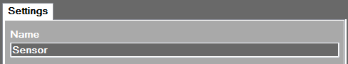
On the Settings tab, type sensor name in the Name text box.
-
On the Available Cameras tab, ensure that the selected camera is highlighted.
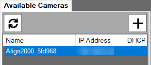
- Click
 to scan the network for visible cameras and sensors.
 - To move the camera to the Settings tab, click
 .
. -
On the Settings tab, ensure that the Master check box is selected.
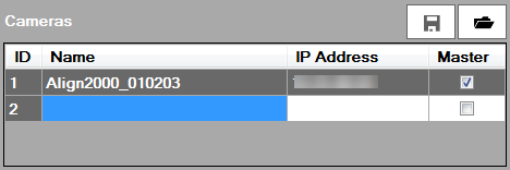 Note: If you add two cameras to a sensor, you must define which camera is used as a Master by selecting the Master check box. You use the other camera as a Slave.
 -
Configure the PLC/Robot Communication settings.
If you use the TCP/IP protocol, select TCP/IP and configure the Port Number PLC/Robot setting.
Enable Message Length Header if you want the sensor to begin the response with a 3-digit header indicating the response length excluding the CR/LF. The CR/LF is in the response but is excluded from the response length.
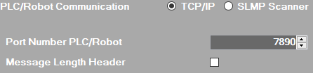
Control Description Port Number PLC/Robot Enter the port number of the TCP/IP server at which you establish the communication between TCP/IP device. If you use the SLMP Scanner protocol, select SLMP Scanner and configure the PLC settings.
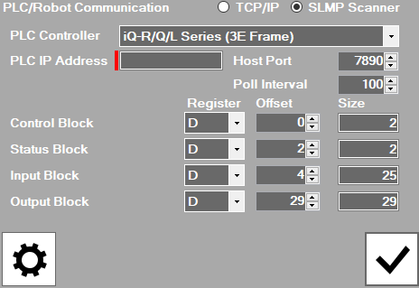
Control Description PLC Controller Select the type of Mitsubishi PLC to communicate with the sensor: iQ-R/Q/L Series (3E Frame) or FX Series (1E Frame). PLC IP Address Enter the IP address of the Mitsubishi PLC that you connect to the sensor. Host Port Enter the TCP port number of the Mitsubishi PLC. Poll Interval Enter the time between successive polls of the Vision Control block on the Mitsubishi PLC in milliseconds. Offset Enter an offset within the device table to read or write the Control Data, Status, Input and Output blocks.
If you use the Ethernet-IP protocol, select Ethernet-IP
.
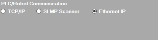
After Ethernet-IP is select, you can now configure communications on the Robot/PLC controller's side.
Note:- The Size field displays the size of data block to communicate with the Mitsubishi PLC. AlignSight has the defined data size for each data block, and you are not allowed to change the value.
- AlignSight does not support the Command and Command Result blocks.
- Click
 . You have configured the sensor.
 -
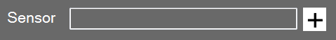
If you add an additional sensor, click
 next to the Sensor field and repeat steps 1 through 6.